Scanning Electron Microscope (SEM) Images Provided Demonstrate Failure Mode
Background
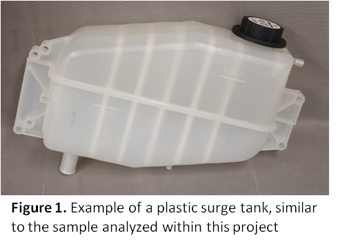
Traditionally metal is the material of choice for fluid reservoirs and fuel tanks, but as the demand for lighter weight materials grow, substituting polymer materials for metal is becoming more commonplace. For instance, in the automotive industry lighter weight equals better gas mileage. Reinforcing polymeric materials with glass fiber can lead to replacement parts that are similar in strength and endurance when compared to their metal equivalents. Blow molded glass fiber reinforced polymer tanks are a cost effective lighter weight solution to metal tanks, if the polymer chosen is resistant to the environmental stresses that it may face. The tank design and molding process must be optimized so that no areas of high stress are molded into the product. Any stresses molded into the tank could lead to cracks in the product, which in turn will lead to a failure.
Polymer Solutions received a request for a failure analysis investigation of a glass fiber reinforced polypropylene surge tank. Our client requested assistance identifying the root cause of observed cracks. To investigate the root cause of the cracks, optical microscopy (OM) and scanning electron microscopy (SEM) were employed. A surge tank sample without any visible cracks was compared to the region of cracking.
Samples
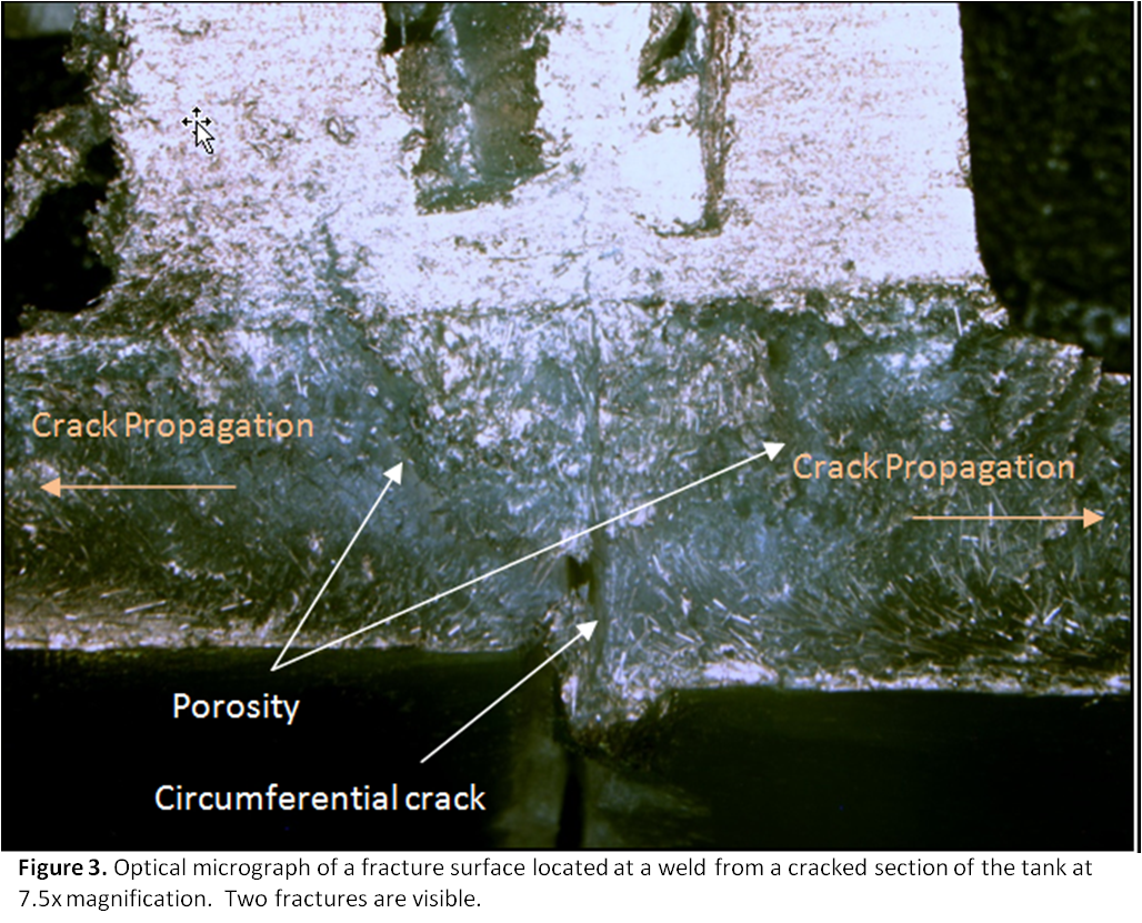
Two cracked areas were sectioned from the tank. Each sample contained an axial and a circumferential crack. Axial cracks travelled across (perpendicular to) the weld line, and circumferential cracks radiated parallel to the weld line. One crack free weld location of the Surge Tank, which contained whitening was sectioned and polished for microscopic analysis.
Optical Microscopy (OM)
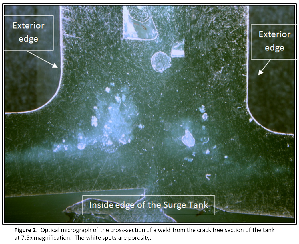
Micrographs were taken of the samples at 7.5x, 10x, and 20x magnification, and examples are shown in Figures 2 through 4. The whitening observed in the polished crack free sample was from porosity. There was no indication after optical microscopy was performed to whether the axial or the circumferential cracks occurred first in the cracked tank samples.
Scanning Electron Microscopy (SEM)
The samples were sputter coated with a 10 nm layer of gold to prevent electrical charging, and SEM was performed on the three samples. SEM micrographs of the crack free area of tank confirmed that the whitening is from porosity in the polymer matrix.
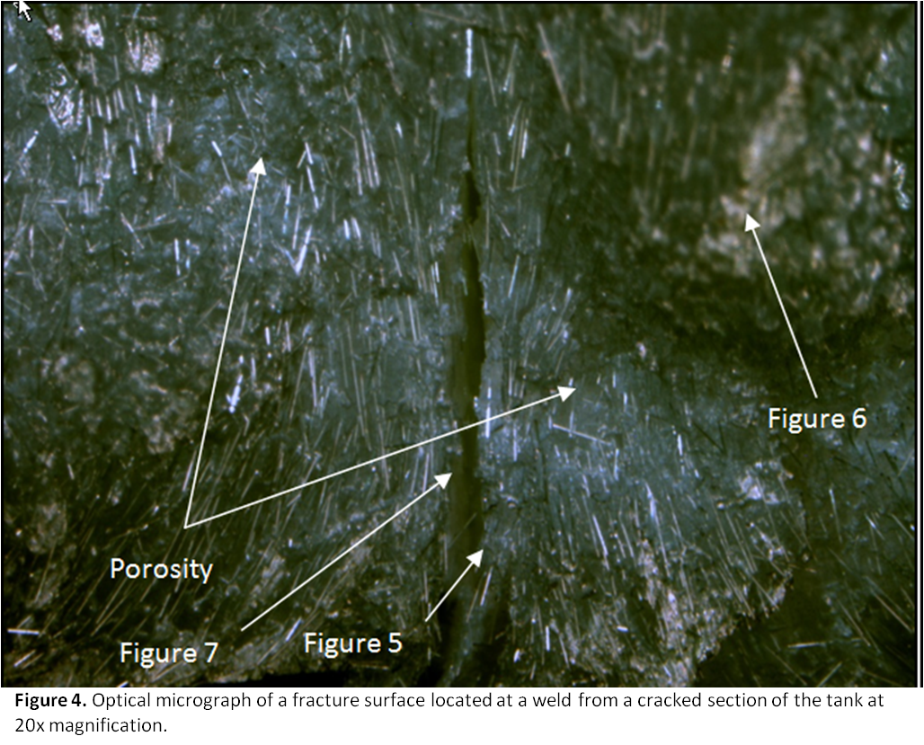
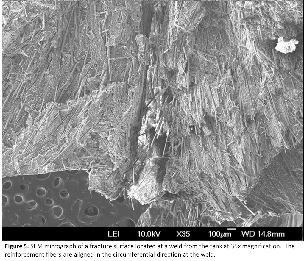
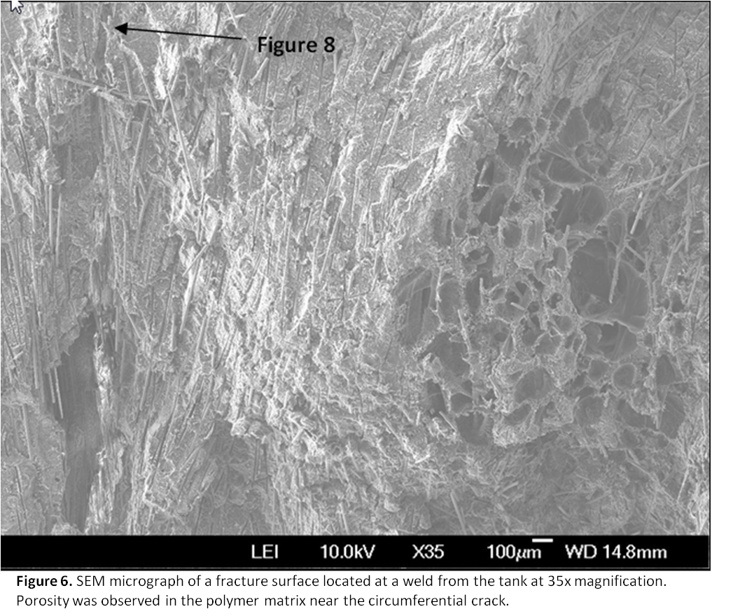
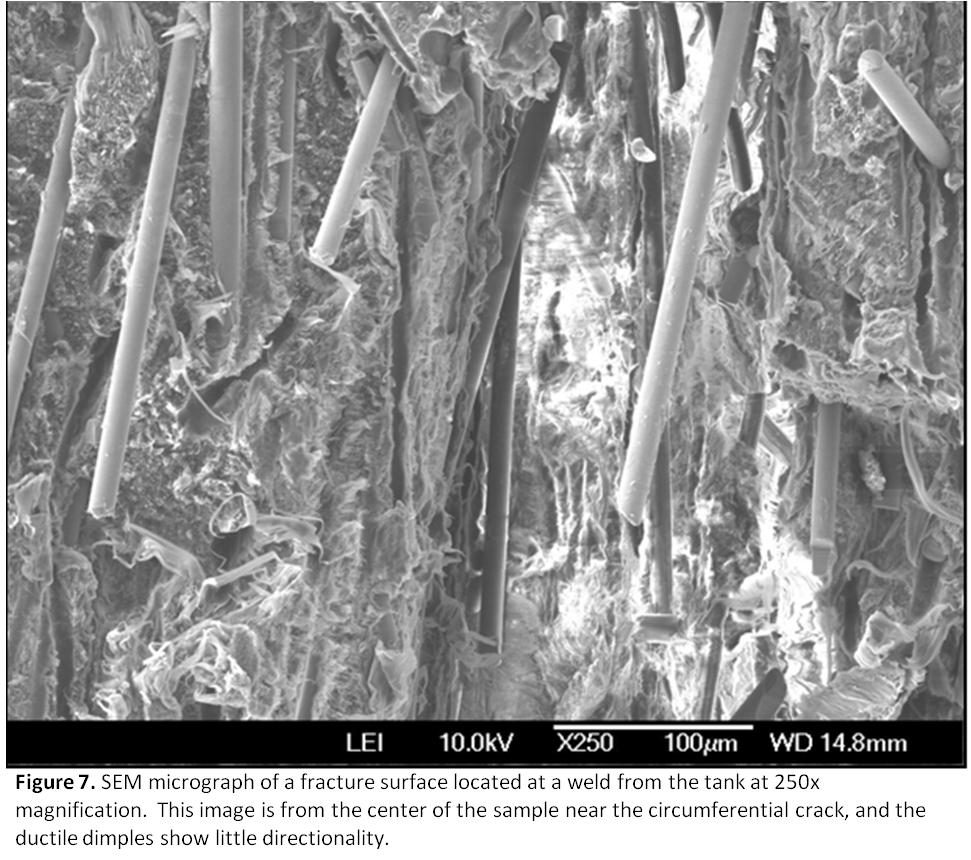
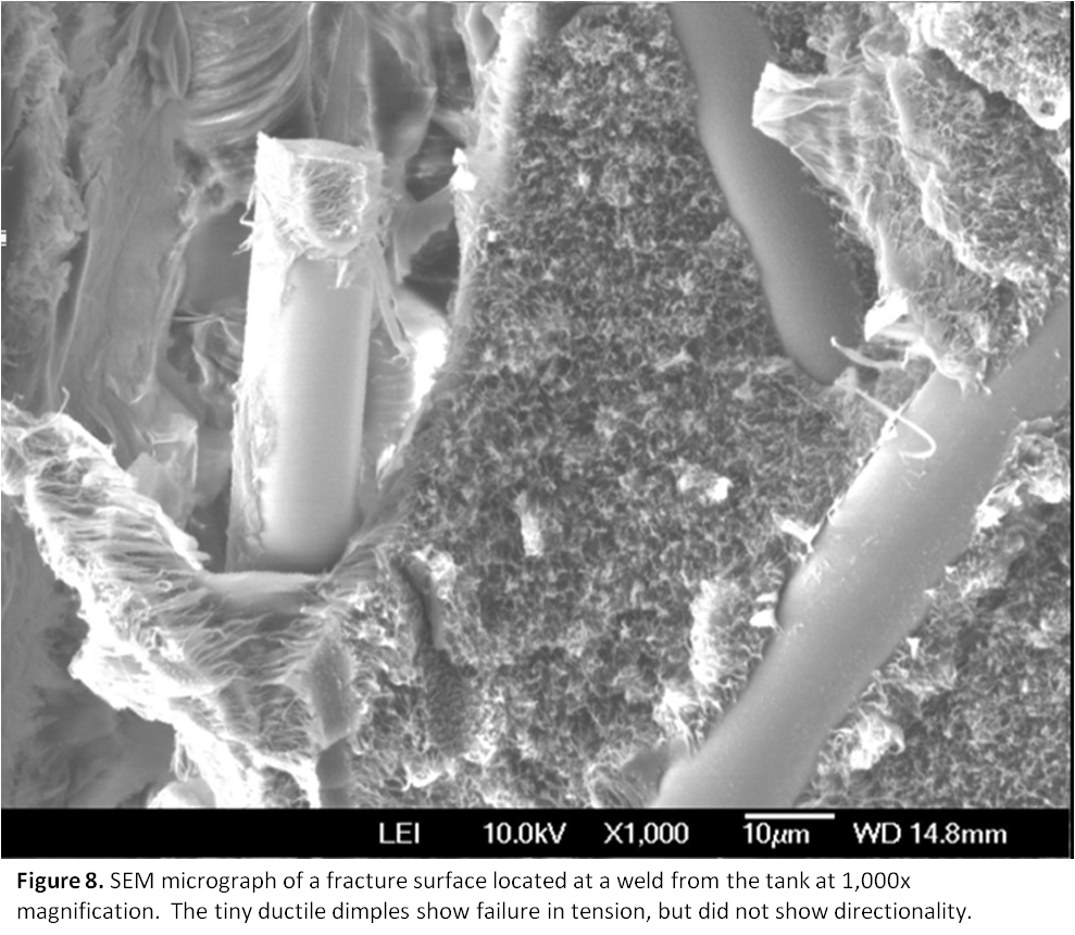
SEM micrographs of the cracked surfaces from the tank showed that the reinforcement fibers were aligned in the circumferential direction at the welds, and there was also significant porosity on both sides of the two circumferential cracks as seen in Figures 5 and 6. Figures 7 and 8 are higher magnification images near one of the circumferential cracks which show ductile dimples that indicate the crack progressed mostly in a pure tension mode.
Conclusions
Microscopy of the Surge Tank sample revealed that the observed whitening was most commonly present in the middle of the sample and caused by porosity in the polymer matrix. Porosity was often located at the weld locations, but it is unclear whether the porosity was formed during the welding process.
The cracks observed in the Surge Tank samples were observed in the corners, which is expected as the corners are stress concentrators. There were two cracks at both locations examined, with one crack travelling in the circumferential direction and the other in the axial direction. Significant porosity was observed on both sides of the circumferential crack, and SEM analysis showed the reinforcement fibers near the circumferential crack were aligned in the circumferential direction, which would prevent significant load transfer in that area from a perpendicular force. The alignment of the fibers and exaggerated porosity in this region appears to directly coincide with the welding process. It was unclear from the fracture surface features whether the circumferential or the axial crack was created first, but it is clear that the cracks originated near the weld and propagated outwards.
The ductile dimples observed on fracture surfaces usually show directionality, and thus it is typically possible to determine which direction the crack progressed. The ductile dimples observed on the Surge Tank fracture surfaces had almost no directionality, which is indicative of almost pure tension failure. This means the fracture most likely initiated in the center of the sample at the voids on either side of the circumferential crack, and then the fracture progressed in both the circumferential and axial directions originating from the weld region.